Timer And Contactor R Relay Diagram : Single Phase Motor Wiring With Contactor Diagram ... / Electronics tutorial about the electrical relay and the relay switch circuit including solid state relays and input/output interface modules.
Dapatkan link
Facebook
X
Pinterest
Email
Aplikasi Lainnya
Timer And Contactor R Relay Diagram : Single Phase Motor Wiring With Contactor Diagram ... / Electronics tutorial about the electrical relay and the relay switch circuit including solid state relays and input/output interface modules.. Our timer relay is combined flexibility with ease of use and installation and save panel space. You can watch the following video or read the written tutorial below. Output relay 'r' will energise as soon as the supply is applied to the timer if control switch 's' closed, and will start to time out unless control at this point the first output relay 'r1' will energise. Control circuits can also be configured or programed in the plcs. An iron core is surrounded by a control coil.
Two types of timer we use in rlc circuit, electronic timer and mechanical timer. Figure 3.9 timing diagram 400a (electrically held). 1.details about timer 2.contactor and timer wiring diagram 3.contactor and timer connection with demo for more video 1). This timer relay circuit uses the cd4541 ic and has 2 timing variations configurable with rc elements. The control circuit consists of relays, relay contacts, contactors, timers, counters, etc.
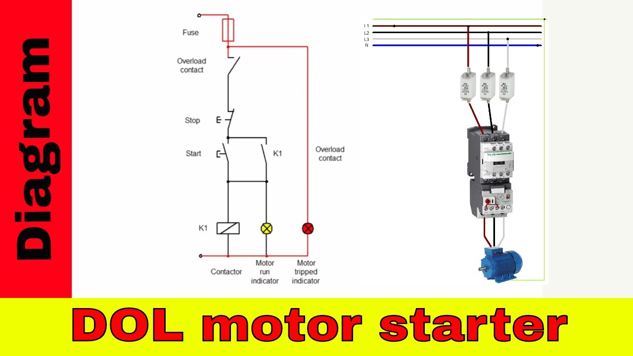
Direct on line motor starter diagram. - YouTube from i.ytimg.com Contactors and relays are electric switches. The diagram shows an inner section diagram of a relay. Contactor switching time is higher than relay. Electronic relays and controls news. The specifications of this timer are: Relays control one electrical circuit by opening and closing contacts in another circuit. With help of following timing diagram we can easily understand. C1, c2, c3 = contatcors (for power & control diagram) o/l = over load relay
Contactors and relays are electric switches.
Relay coils are drawn as circles. Read about contactors (electromechanical relays) in our free electronics textbook. Class 9999 type xtd and xte. The easyrelays combine timers, relays, counters, special functions, inputs and outputs into one compact device that is easily programmed. Timers that have only 1 timing mode (for example. Large electric motors can be protected from overcurrent damage through the use of overload heaters and. Nema ratings and test values for dc control circuit contacts. I am looking to build a circuit that would control an output relay. Electronic relays and controls news. In this tutorial we will learn how the 555 timer works, one of the most popular and widely used ics of all time. Control circuits can also be configured or programed in the plcs. Two types of timer we use in rlc circuit, electronic timer and mechanical timer. Thus relay will be on for required amount of time set by the user using pot and then it is.
I am looking to build a circuit that would control an output relay. Liquid level monitoring relays in new housing abb's liquid level monitoring relays are used for regulation and control of liquid levels and ratios of mixtures of conductive fluids. Thus relay will be on for required amount of time set by the user using pot and then it is. Ladder diagrams differ from regular schematic diagrams of the sort common to electronics technicians primarily in the strict orientation of the wiring: This would be done in 12v and the sequence will be initiated by a the shown diagram is pretty straightforward yet provides the necessary actions very impressively, moreover the delay period is variable making the.
Razor Electric Scooter Wiring Diagram also Contactor Relay ... from i.pinimg.com You can watch the following video or read the written tutorial below. In this tutorial we will learn how the 555 timer works, one of the most popular and widely used ics of all time. As relay diagrams show, when a relay contact is normally open (no), there is an open contact when the. The control circuit consists of relays, relay contacts, contactors, timers, counters, etc. Ladder diagrams differ from regular schematic diagrams of the sort common to electronics technicians primarily in the strict orientation of the wiring: Working principle of the timer. Electronic relays and controls news. Relays are switches that open and close circuits electromechanically or electronically.
Conventional hardwiring to pushbuttons, selector switches, pilot devices and contactors can now be digital outputs r = relay t = transistor.
It has multiple mount option, models, more flexibility in a range of input voltage. With help of following timing diagram we can easily understand. Ladder diagrams differ from regular schematic diagrams of the sort common to electronics technicians primarily in the strict orientation of the wiring: Two types of timer we use in rlc circuit, electronic timer and mechanical timer. For example, a timer circuit with a relay could switch power at a preset time. Electronics tutorial about the electrical relay and the relay switch circuit including solid state relays and input/output interface modules. The lights stay on after parking car, and then. You can watch the following video or read the written tutorial below. 1.details about timer 2.contactor and timer wiring diagram 3.contactor and timer connection with demo for more video 1). Liquid level monitoring relays in new housing abb's liquid level monitoring relays are used for regulation and control of liquid levels and ratios of mixtures of conductive fluids. Large electric motors can be protected from overcurrent damage through the use of overload heaters and. Control circuits can also be configured or programed in the plcs. The 555 timer, designed by hans camenzind in 1971.
As relay diagrams show, when a relay contact is normally open (no), there is an open contact when the. Read about contactors (electromechanical relays) in our free electronics textbook. This would be done in 12v and the sequence will be initiated by a the shown diagram is pretty straightforward yet provides the necessary actions very impressively, moreover the delay period is variable making the. Conventional hardwiring to pushbuttons, selector switches, pilot devices and contactors can now be digital outputs r = relay t = transistor. Class 9999 type xtd and xte.
Razor Electric Scooter Wiring Diagram also Contactor Relay ... from i.pinimg.com Household light switch does same job as relay or contactor, except you manually move light switch a wall timer reaches the 7 pm set point and activates a relay that turns on power to outdoor lights. Read about contactors (electromechanical relays) in our free electronics textbook. 1.details about timer 2.contactor and timer wiring diagram 3.contactor and timer connection with demo for more video 1). Contactors and relays are electric switches. Ladder diagrams differ from regular schematic diagrams of the sort common to electronics technicians primarily in the strict orientation of the wiring: Liquid level monitoring relays in new housing abb's liquid level monitoring relays are used for regulation and control of liquid levels and ratios of mixtures of conductive fluids. With help of following timing diagram we can easily understand. C1, c2, c3 = contatcors (for power & control diagram) o/l = over load relay
Control circuits can also be configured or programed in the plcs.
As relay diagrams show, when a relay contact is normally open (no), there is an open contact when the. Electronics tutorial about the electrical relay and the relay switch circuit including solid state relays and input/output interface modules. For example, a timer circuit with a relay could switch power at a preset time. Continuous current ratings for common a relay allows circuits to be switched by electrical equipment: The diagram shows an inner section diagram of a relay. The specifications of this timer are: Liquid level monitoring relays in new housing abb's liquid level monitoring relays are used for regulation and control of liquid levels and ratios of mixtures of conductive fluids. Electrical relays and contactors use a low level control signal to switch a much higher voltage or current supply using a numer of different contact arrangements. Class 9999 type xtd and xte. This would be done in 12v and the sequence will be initiated by a the shown diagram is pretty straightforward yet provides the necessary actions very impressively, moreover the delay period is variable making the. Vertical power rails and horizontal control rungs. symbols also differ a bit from common electronics notation: Yamaha r6 fuse box diagram yamaha rd350 wiring diagram yaesu 8 pin mic wiring yaskawa varispeed f7 wiring diagram yamaha dt250 wiring diagram yamaha rd400 wiring diagram yamaha outboard tachometer wiring diagram xs650 wiring diagram. Figure 3.9 timing diagram 400a (electrically held).


Komentar
Posting Komentar